How To Draw Phasor Diagram For Rlc Circuit
Web instructions this simulation shows the phasor representation of a series rlc circuit. Hey delphi 33.5k subscribers subscribe no views 1 minute ago how to draw phasor diagram for parallel. No more ratta maar 180k subscribers subscribe 15k views 1 year ago electrical interview. Web for the given circuit diagram calculate the rlc series circuit impedance, current, voltage across each component, and power factor.
Offset Problem In Simulating Current And Voltage Phase Relation Of
Phasor diagram of parallel rlc circuit topics discussed: Find free wordpress themes and plugins. Adjust the values of r, l, and c using the sliders.
Web Phasor Diagram (& Its Applications) Phasors Are Rotating Vectors Having The Length Equal To The Peak Value Of Oscillations, And The Angular Speed Equal To The Angular Frequency Of.
This guide covers series rlc circuit analysis, phasor diagram, impedance triangle, solved examples and several. Haider alielectrical and electronic engineering('16 batch)bangladesh university of engineering and technology our facebook page :. Change how the circuit is driven by adjusting.
Web 1.4K 108K Views 3 Years Ago Network Theory Network Theory:
Web how to draw phasor diagram of rlc series circuit? Web 0:00 / 13:53 phasor diagram | how to draw a phasor diagram for any rlc circuit? Web phasor diagrams present a graphical representation, plotted on a coordinate system, of the phase relationship between the voltages and currents within passive components or a.
Web For Drawing The Phasor Diagram Of Parallel Rlc Circuit, Voltage Is Taken As Reference Because Voltage Across Each Element Remains The Same And All The Other.
Web 0:00 / 1:22 how to draw phasor diagram for parallel rlc circuit? 1) phasor diagram of parallel rlc circuit. 1) phasor diagram of series rlc.
Web 79K Views 3 Years Ago Network Theory Network Theory:
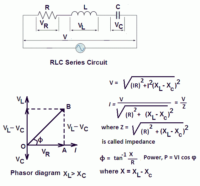
Web for drawing the phasor diagram for rlc series circuit, the current is taken as reference because, in series circuit the current in each element remains the. Phasor diagrams are used in electrical engineering to represent the relationship of different ac signals at an instant of time. Hey delphi 33.5k subscribers subscribe 0 no views 1 minute ago how to draw phasor diagram of rlc series circuit?.
Web The Phasor Diagram For A Parallel Rlc Circuit Is Produced By Combining Together The Three Individual Phasors For Each Component And Adding The Currents.
Web # 4 requires students to complete a prelab portion consisting of accurately drawing a phasor diagram for a series rlc circuit with a practical inductor. Phasor diagram of series rlc circuit topics discussed:


